Thursday, June 25, 2009

How to Surface-enable the ArcGIS API for WPF

The Applications Prototype Lab at ESRI have created a few proof-of-concepts for the Surface using the ArcGIS API for WPF.  Examples of which can be seen here and here.

Surface applications are essentially WPF applications running in full screen mode.  When a user interacts with an application on a Surface device is not through the standard mouse API but through a specific Surface API.  The code below describes how to Surface-enable the map control that comes with the ArcGIS API for WPF.  This is just a basic implementation and should be treated as a developer sample rather than anything official.

SurfaceMap.xaml

After installing the Microsoft Surface SDK 1.0 (or 1.1) you will see a few extra items in the new projects dialog of Microsoft Visual Studio 2008.  Select Surface Application, add a reference to the ArcGIS API for WPF assemblies and then add a new resource file called SurfaceMap.xaml.  Ensure that the build action is set to page.

<ResourceDictionary
 xmlns="http://schemas.microsoft.com/winfx/2006/xaml/presentation"
 xmlns:local="clr-namespace:ESRI.PrototypeLab.Surface.Ccm"
 xmlns:x="http://schemas.microsoft.com/winfx/2006/xaml"
 xmlns:s="http://schemas.microsoft.com/surface/2008"
 xmlns:esri="clr-namespace:ESRI.ArcGIS.Client;assembly=ESRI.ArcGIS.Client"
    >
    <Style TargetType="{x:Type local:SurfaceMap}">
        <Setter Property="Template">
            <Setter.Value>
                <ControlTemplate TargetType="{x:Type local:SurfaceMap}">
                    <Border
Background="{TemplateBinding Background}" BorderBrush="{TemplateBinding BorderBrush}" BorderThickness="{TemplateBinding BorderThickness}" Width="{TemplateBinding Width}" Height="{TemplateBinding Height}" > <esri:Map Name="PART_map"
PanDuration="0"
ZoomDuration="0" /> </Border> </ControlTemplate> </Setter.Value> </Setter> </Style> </ResourceDictionary>

App.xaml

Next you need to inform the compiler to load SurfaceMap.xaml as a resource.  To do so, add an entry to the App.xaml file as shown below.

<Application x:Class="ESRI.PrototypeLab.Surface.Ccm.App"
    xmlns="http://schemas.microsoft.com/winfx/2006/xaml/presentation"
    xmlns:x="http://schemas.microsoft.com/winfx/2006/xaml"
    StartupUri="SurfaceWindow1.xaml"
    >
    <Application.Resources>
        <ResourceDictionary>
            <ResourceDictionary.MergedDictionaries>
                <ResourceDictionary Source="...generic.xaml"/>
                <ResourceDictionary
Source="/ESRI.PrototypeLab.Surface.Ccm;component/SurfaceMap.xaml"/> </ResourceDictionary.MergedDictionaries> </ResourceDictionary> </Application.Resources> </Application>

SurfaceMap.cs

Add a new code file called SurfaceMap.cs and make sure that the build action is set to compile.  The code below contains the bulk of the logic to interpret contact (i.e. finger) manipulation.  The two key points to note is the manipulation processor and the inertia processor.  The manipulation processor will raise events when users manipulate performs a panning or zooming action.  The inertia processor is used to continue panning if the user flicks map.

using System;
using System.Windows;
using System.Windows.Input;
using ESRI.ArcGIS.Client;
using ESRI.ArcGIS.Client.Geometry;
using Microsoft.Surface.Presentation;
using Microsoft.Surface.Presentation.Controls;
using Microsoft.Surface.Presentation.Manipulations;
using Microsoft.Surface;

namespace ESRI.PrototypeLab.Surface.Ccm {
    public partial class SurfaceMap : SurfaceUserControl {
        private Map m_map = null;
        private Affine2DManipulationProcessor
m_manipulationProcessor = null; private Affine2DInertiaProcessor m_inertiaProcessorMove = null; static SurfaceMap() { FrameworkElement.DefaultStyleKeyProperty.OverrideMetadata(
typeof(SurfaceMap),
new FrameworkPropertyMetadata(typeof(SurfaceMap))); } public SurfaceMap() : base() { // Define manipulation processor used or panning and Zooming this.m_manipulationProcessor =
new Affine2DManipulationProcessor( Affine2DManipulations.TranslateX | Affine2DManipulations.TranslateY | Affine2DManipulations.Scale, this, true); this.m_manipulationProcessor.Affine2DManipulationStarted +=
new EventHandler<Affine2DOperationStartedEventArgs>
(this.ManipulationProcessor_Affine2DManipulationStarted); this.m_manipulationProcessor.Affine2DManipulationDelta +=
new EventHandler<Affine2DOperationDeltaEventArgs>
(this.ManipulationProcessor_Affine2DManipulationDelta); this.m_manipulationProcessor.Affine2DManipulationCompleted +=
new EventHandler<Affine2DOperationCompletedEventArgs>
(this.ManipulationProcessor_Affine2DManipulationCompleted); // Define inertia proceesor for panning this.m_inertiaProcessorMove = new Affine2DInertiaProcessor(); this.m_inertiaProcessorMove.Affine2DInertiaDelta +=
new EventHandler<Affine2DOperationDeltaEventArgs>
(this.InertiaProcessorMove_Affine2DInertiaDelta); this.m_inertiaProcessorMove.Affine2DInertiaCompleted +=
new EventHandler<Affine2DOperationCompletedEventArgs>
(this.InertiaProcessorMove_Affine2DInertiaCompleted); } public override void OnApplyTemplate() { base.OnApplyTemplate(); this.m_map = (Map)this.Template.FindName("PART_map", this); } public Map Map { get { return this.m_map; } set { this.m_map = value; } } protected override void OnContactDown(ContactEventArgs e) { base.OnContactDown(e); if (!e.Contact.IsFingerRecognized) { return; } e.Contact.Capture(this, CaptureMode.SubTree); this.m_manipulationProcessor.BeginTrack(e.Contact); e.Handled = true; } protected override void OnContactChanged(ContactEventArgs e) { base.OnContactChanged(e); if (!e.Contact.IsFingerRecognized) { return; } Point position = e.Contact.GetPosition(this); if (position.X < 0 || position.Y < 0 || position.X > this.ActualWidth || position.Y > this.ActualHeight) { e.Contact.Capture(this, CaptureMode.None); e.Handled = true; return; } e.Contact.Capture(this, CaptureMode.SubTree); this.m_manipulationProcessor.BeginTrack(e.Contact); e.Handled = true; } protected override void OnContactUp(ContactEventArgs e) { base.OnContactUp(e); if (!e.Contact.IsFingerRecognized) { return; } e.Contact.Capture(this, CaptureMode.None); } private void ManipulationProcessor_Affine2DManipulationStarted(
object sender, Affine2DOperationStartedEventArgs e) { if (this.m_inertiaProcessorMove.IsRunning) { this.m_inertiaProcessorMove.End(); } } private void ManipulationProcessor_Affine2DManipulationDelta(
object sender, Affine2DOperationDeltaEventArgs e) { if (this.m_map == null) { return; } if (this.m_map.Extent == null) { return; } if ((e.Delta.X == 0) &&
(e.Delta.Y == 0) &&
(e.ScaleDelta == 0)) { return; } if ((e.Delta.X != 0) || (e.Delta.Y != 0)) { MapPoint center = this.m_map.Extent.GetCenter(); Point screen = this.m_map.MapToScreen(center); Point newScreen; switch(ApplicationLauncher.Orientation){ case UserOrientation.Top: // Surface is upside-down newScreen = Point.Add(screen, e.Delta); break; case UserOrientation.Bottom: // Surface has normal orientation newScreen = Point.Subtract(screen, e.Delta); break; default: return; } MapPoint newCenter = this.m_map.ScreenToMap(newScreen); this.m_map.PanTo(newCenter); Window w = SurfaceWindow.GetWindow(this); } if (e.ScaleDelta != 0) { if (Contacts.GetContactsCaptured(this).Count > 1) { this.m_map.ZoomToResolution(
this.m_map.Resolution / e.ScaleDelta); } } } private void ManipulationProcessor_Affine2DManipulationCompleted(
object sender, Affine2DOperationCompletedEventArgs e) { this.m_inertiaProcessorMove.InitialOrigin = new Point(0, 0); this.m_inertiaProcessorMove.InitialVelocity = e.Velocity * 10; this.m_inertiaProcessorMove.DesiredDeceleration = 0.005; this.m_inertiaProcessorMove.Begin(); } private void InertiaProcessorMove_Affine2DInertiaDelta(
object sender, Affine2DOperationDeltaEventArgs e) { if ((e.Velocity.X == 0) && (e.Velocity.Y == 0)) { return; } MapPoint center = this.m_map.Extent.GetCenter(); Point screen = this.m_map.MapToScreen(center); Point newScreen; switch (ApplicationLauncher.Orientation) { case UserOrientation.Top: // Surface is upside-down newScreen = Point.Add(screen, e.Velocity); break; case UserOrientation.Bottom: // Surface has normal orientation newScreen = Point.Subtract(screen, e.Velocity); break; default: return; } MapPoint newCenter = this.m_map.ScreenToMap(newScreen); this.m_map.PanTo(newCenter); } private void InertiaProcessorMove_Affine2DInertiaCompleted(
object sender, Affine2DOperationCompletedEventArgs e) { } } }

SurfaceWindow1.xaml

The snippet below demonstrates how to add a reference to the SurfaceMap defined in the snippets above.

<s:SurfaceWindow
    x:Class="ESRI.PrototypeLab.Surface.Ccm.SurfaceWindow1"
    xmlns="http://schemas.microsoft.com/winfx/2006/xaml/presentation"
    xmlns:x="http://schemas.microsoft.com/winfx/2006/xaml"
    xmlns:s="http://schemas.microsoft.com/surface/2008"
    xmlns:local="clr-namespace:ESRI.PrototypeLab.Surface.Ccm"
    Title="my Title"
    Height="768"
    Width="1024"
    Loaded="SurfaceWindow_Loaded"
    >
    <Grid>
        <local:SurfaceMap x:Name="surfaceMap" />
    </Grid>
</s:SurfaceWindow>

SurfaceWindow1.xaml.cs (code behind)

In the code-behind of the Surface window, the map extent is defined and the ArcGIS Online world street map layer is added.

private void SurfaceWindow_Loaded(object sender, RoutedEventArgs e) {
    // Add the ArcGIS Online street map
    ArcGISTiledMapServiceLayer streets = new ArcGISTiledMapServiceLayer(){
        ID = "street",
        Url = "http://server.arcgisonline.com/ArcGIS/rest/services" +
"/ESRI_StreetMap_World_2D/MapServer"
, Opacity = 1 }; this.surfaceMap.Map.Extent =
new Envelope(-116.992383, 33.126732, -116.560400, 32.797143); this.surfaceMap.Map.Layers.Add(streets); // Listen to map events this.surfaceMap.Map.ExtentChanging +=
new EventHandler<ExtentEventArgs>(this.Map_ExtentChanging); this.surfaceMap.Map.ExtentChanged +=
new EventHandler<ExtentEventArgs>(this.Map_ExtentChanged); }

This concludes this tutorial on adding Surface support to the ArcGIS API for WPF map control. For more information, please visit the ArcGIS API for Silverlight/WPF home page, support forum and resource center.

Cross Country Mobility for Microsoft Surface

Yesterday the Applications Prototype Lab at ESRI released demonstration videos of two Microsoft Surface applications.  The first was a demonstration of a simulated police dispatcher (announced here) and the second is a cross country mobility application discussed in this post.

This Surface application is built with ESRI’s ArcGIS API for WPF and references map and geoprocessing services from ArcGIS Server.  Cross country mobility is the name giving to an exercise of determining the most efficient path between two locations.  Depending on the data (and parameters) the end user can find a route that is the fastest, shortest, most fuel efficient, avoids urban areas, flattest or any other condition.

The first step illustrated in the video is the rating of three geographic layers: slope, vegetation and transportation.  The user can assign a preference to weight one more than others.  For example, slope could be a larger consideration if moving heavy equipment than the vegetation type.  Secondly, items within each layer can also be rated.  For example, the user can indicate that low slope is preferable to steep slopes and that grades great than 40° are “no go” (or impossible to traverse).

The next step is to indicate the intended target location for the three flagged vehicles/people/units.  In the demonstration video the target is represented by a bulls eye button than can dragged into position.

After the three geographic layer have been rated and the target placed into position, a request is sent to ArcGIS Server to perform a weighted overlay using the user defined parameters.  The result is a new geographic layer called a cost surface.  A cost surface is like an image where each pixel contains a cost value, that is, the cost for an object to traverse it.

The next step, uses the cost surface to find the least cost path from the three flagged objects to the target.

The final step is the creation of a cost corridor.  A cost corridor is an area around the least cost path with a plus or minus one, two and three percent variation.  Basically, what alternative path could the three flagged objects take by sacrificing one to three percent cost (in time, money, fuel etc).

This is a very brief discussion of one of many geoprocessing capabilities in the ArcGIS product suite.  I would encourage you to explore this exciting technology at the ESRI website.

Police Dispatcher on Microsoft Surface

In May 2009, the Applications Prototype Lab published a web application called “Police Dispatcher”.  The application simulated a police dispatch system with real time incidents and the tracking of police vehicles.  The application was built using Silverlight 2 and the ArcGIS API for Silverlight.

Police Dispatcher for Microsoft Silverlight

The police dispatcher demonstration was recently ported to the Microsoft Surface as a Surface application.  Surface applications are similar to standard WPF application except that they target the Surface hardware and include references to a few extra libraries.  The transition was relatively trivial, for example, the application references the ArcGIS API for WPF rather than the ArcGIS API for Silverlight.

In the Surface application we took advantage of some the goodness of WPF such as drop shadows and glow bitmap effects.

Saturday, May 16, 2009

Exploiting the ESRI Projection Engine

The ESRI products ArcGIS Explorer, ArcGIS Desktop and ArcGIS Engine ship with an extremely useful C DLL called the projection engine Library.  The projection engine is used by these products to perform geodetic (or ellipsoidal) computations.

The projection engine is fully documented in the SDE C API and there is a sample VB6 wrapper for two functions on the EDN web site.

The VB6 sample be easily ported to C# using DLLImportAttribute.  However there are two disadvantages of using DLLImport.

  1. DLLs are loaded into memory each time a function is called,
  2. The file and path name to the DLL is hard coded at design time.

However with .NET 2.0 a new method called GetDelegateForFunctionPointer was added to the Marshal class to allow late binding. This meant that external DLLs could be discovered and loaded at runtime.

Below is a C# wrapper to the ESRI Projection Engine.  The wrapper is developed as a singleton so that the DLL is only loaded once per application instance.  Additionally, the location of the projection engine library is discovered at runtime from the registry.

Here is a example using the projection engine singleton for ArcGIS Explorer to calculate the geodetic distance between London and Paris.  The geodetic distance is the shortest distance between two points on the surface of an ellipsoid.

public class ProjectionEngineTest{
    public void Main() {
        double distance = 0d;
        double azimuthForward = 0d;
        double azimuthBack = 0d;
        ProjectionEngine projectionEngine = ProjectionEngineExplorer.GetInstance();
        projectionEngine.GetGeodesicDistance(
            ProjectionEngine.GLOBERADIUS,
            0,
            ProjectionEngine.ToRadians(51.50d),
            ProjectionEngine.ToRadians(-0.12d),
            ProjectionEngine.ToRadians(48.86d),
            ProjectionEngine.ToRadians(2.35d),
            out distance,
            out azimuthForward,
            out azimuthBack);
        MessageBox.Show(string.Format("London to Paris is {0} meters", distance.ToString()));               
    }
}

image

Here is the source code to the wrappers.

Please note that the code and methodology used in this post is not endorsed or supported by ESRI. Use this code at your own risk.

using System;
using System.Collections.Generic;
using System.IO;
using System.Runtime.InteropServices;
using System.Text;
using System.Windows.Forms;
using Microsoft.Win32;

namespace ESRI.ArcGIS.Sample {
    /// <summary>
    /// Projection Engine Abstract Class
    /// </summary>
    public abstract class ProjectionEngine {
        public const double GLOBERADIUS = 6367444.65712259d;
        private GeodesicDistance m_gd = null;
        private GeodesicCoordinate m_gc = null;

        [DllImport("kernel32.dll")]
        private static extern IntPtr LoadLibrary(String dllname);

        [DllImport("kernel32.dll")]
        private static extern IntPtr GetProcAddress(IntPtr hModule, String procname);

        private delegate void GeodesicDistance(
            [In] double semiMajorAxis,
            [In] double eccentricity,
            [In] double longitude1,
            [In] double latitude1,
            [In] double longitude2,
            [In] double latitude2,
            [Out] out double distance,
            [Out] out double azimuthForward,
            [Out] out double azimuthBack);

        private delegate void GeodesicCoordinate(
            [In] double semiMajorAxis,
            [In] double eccentricity,
            [In] double longitude1,
            [In] double latitude1,
            [In] double distance,
            [In] double azimuth,
            [Out] out double longitude2,
            [Out] out double latitude2);
        //
        // CONSTRUCTOR
        //
        protected ProjectionEngine() {
            IntPtr pe = ProjectionEngine.LoadLibrary(this.DLLPath);
            IntPtr gd = ProjectionEngine.GetProcAddress(pe, "pe_geodesic_distance");
            IntPtr gc = ProjectionEngine.GetProcAddress(pe, "pe_geodesic_coordinate");

            this.m_gd = (GeodesicDistance)Marshal.GetDelegateForFunctionPointer(
                gd, typeof(GeodesicDistance));
            this.m_gc = (GeodesicCoordinate)Marshal.GetDelegateForFunctionPointer(
                gc, typeof(GeodesicCoordinate));
        }
        //
        // PUBLIC METHODS
        //
        public abstract string DLLPath { get;}
        //
        // PUBLIC METHODS
        //
        /// <summary>
        /// Returns the geodestic azimuth and distance between two geographic locations.
        /// </summary>
        /// <param name="semiMajorAxis">Semi Major Axis</param>
        /// <param name="eccentricity">Globe Eccentricity</param>
        /// <param name="longitude1">From Longitude (radians)</param>
        /// <param name="latitude1">From Latitude (radians)</param>
        /// <param name="longitude2">To Longitude (radians)</param>
        /// <param name="latitude2">To Latitude (radians)</param>
        /// <param name="distance">Returned Geodetic Distance</param>
        /// <param name="azimuthForward">Returned Forward Azimuth (radians)</param>
        /// <param name="azimuthBack">Returned Reverse Azimuth (radians)</param>
        public void GetGeodesicDistance(
            double semiMajorAxis,
            double eccentricity,
            double longitude1,
            double latitude1,
            double longitude2,
            double latitude2,
            out double distance,
            out double azimuthForward,
            out double azimuthBack) {
            this.m_gd(
                semiMajorAxis,
                eccentricity,
                longitude1,
                latitude1,
                longitude2,
                latitude2,
                out distance,
                out azimuthForward,
                out azimuthBack);
        }
        /// <summary>
        /// Returns the geographic location based on the azimuth and distance from another geographic location
        /// </summary>
        /// <param name="semiMajorAxis">Semi Major Axis</param>
        /// <param name="eccentricity">Globe Eccentricity</param>
        /// <param name="longitude1">From Longitude (radians)</param>
        /// <param name="latitude1">From Latitude (radians)</param>
        /// <param name="distance">Distance from "From Location"</param>
        /// <param name="azimuth">Azimuth from "From Location"</param>
        /// <param name="longitude2">Out Logitude (in radians)</param>
        /// <param name="latitude2">Out Latitude (in radians)</param>
        public void GetGeodesicCoordinate(
            double semiMajorAxis,
            double eccentricity,
            double longitude1,
            double latitude1,
            double distance,
            double azimuth,
            out double longitude2,
            out double latitude2) {
            this.m_gc(
                semiMajorAxis,
                eccentricity,
                longitude1,
                latitude1,
                distance,
                azimuth,
                out longitude2,
                out latitude2);
        }
        /// <summary>
        /// Converts Radians to Decimal Degrees.
        /// </summary>
        /// <param name="degrees">In angle in decimal degrees.</param>
        /// <returns>Returns angle in radians.</returns>
        public static double ToRadians(double degrees) { return degrees * (Math.PI / 180d); }
        /// <summary>
        /// Converts Radians to Decimal Degrees.
        /// </summary>
        /// <param name="radians">In angle in radians.</param>
        /// <returns>Returns angle in decimal degrees.</returns>
        public static double ToDegrees(double radians) { return radians * (180d / Math.PI); }
    }
    /// <summary>
    /// Projection Engine Singleton for ArcGIS Explorer
    /// </summary>
    public sealed class ProjectionEngineExplorer : ProjectionEngine {
        private static ProjectionEngineExplorer projectionEngine;
        //
        // PUBLIC METHODS
        //
        public static ProjectionEngineExplorer GetInstance() {
            if (projectionEngine == null) {
                projectionEngine = new ProjectionEngineExplorer();
            }
            return projectionEngine;
        }
        public override string DLLPath {
            get {
                RegistryKey coreRuntime = Registry.LocalMachine.OpenSubKey(
                    @"SOFTWARE\ESRI\E2\CoreRuntime", false);
                object installDir = coreRuntime.GetValue("InstallDir", null);
                coreRuntime.Close();
                string folder = installDir.ToString();
                string bin = Path.Combine(folder, "bin");
                string pedll = Path.Combine(bin, "pe.dll");
                return pedll;
            }
        }
    }
    /// <summary>
    /// Projection Engine Singleton for ArcGIS Desktop
    /// </summary>
    public sealed class ProjectionEngineDesktop : ProjectionEngine {
        private static ProjectionEngineDesktop projectionEngine;
        //
        // PUBLIC METHODS
        //
        public static ProjectionEngineDesktop GetInstance() {
            if (projectionEngine == null) {
                projectionEngine = new ProjectionEngineDesktop();
            }
            return projectionEngine;
        }
        public override string DLLPath {
            get {
                RegistryKey coreRuntime = Registry.LocalMachine.OpenSubKey(
                    @"SOFTWARE\ESRI\CoreRuntime", false);
                object installDir = coreRuntime.GetValue("InstallDir", null);
                coreRuntime.Close();
                string folder = installDir.ToString();
                string bin = Path.Combine(folder, "bin");
                string pedll = Path.Combine(bin, "pe.dll");
                return pedll;
            }
        }
    }
}

ArcGIS Diagrammer - Reverse Engineering a Geodatabase to a Diagram

This post will describe how to create a ready-to-print diagram of your geodatabase in four easy steps.

This exercise will use ArcGIS Diagrammer (free) which is available from ArcScripts.  Prerequisites for ArcGIS Diagrammer include ArcGIS Desktop 9.2 and Microsoft .NET Framework 2.0.

Step 1: Export an existing geodatabase to an ESRI XML Workspace Document

Right click on a personal geodatabase, file geodatabase or an SDE connection. Select Export > XML Workspace Document...

image

Select Schema Only and enter an output file name.  For example C:\Temp\Montgomery.xml. Click Next.

image

Click Finish to start the export.

image

Step 2: Load the XML Workspace Document into ArcGIS Diagrammer

Start ArcGIS Diagrammer by clicking:
START > All Programs > ArcGIS > ArcGIS Diagrammer > ArcGIS Diagrammer

clip_image002

Drag and drop the XML file created by ArcCatalog into the ArcGIS Diagrammer canvas.

image

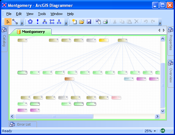
ArcGIS Diagrammer will render all the geodatabase objects and associations.  You may want to change the diagram scale, for example, to change the zooming scale to 25% click View > Zoom > 25%.

image

Step 3: Arrange geodatabase objects

All geodatabase objects can be re-arranged to suit your needs.  Also, some objects like subtypes, domains and feature classes can be expanded to reveal additional details.

image

Step 4: Print the Diagram

Before printing or plotting the diagram you may want to specify a printer/plotter and paper size.  Click File > Print Setup...

image

In the Printer Setup dialog select a printer and paper size.

image

Finally, click File > Print to send the diagram for printing/plotting.

image